Company Address: Phase III of Software Park, Jimei District, Xiamen City, Fujian Province
Add Time: 2025-07-30
Details
BL20-E-GW-EN-IP Gateway Module: Specifications & Features
1. Basic Information
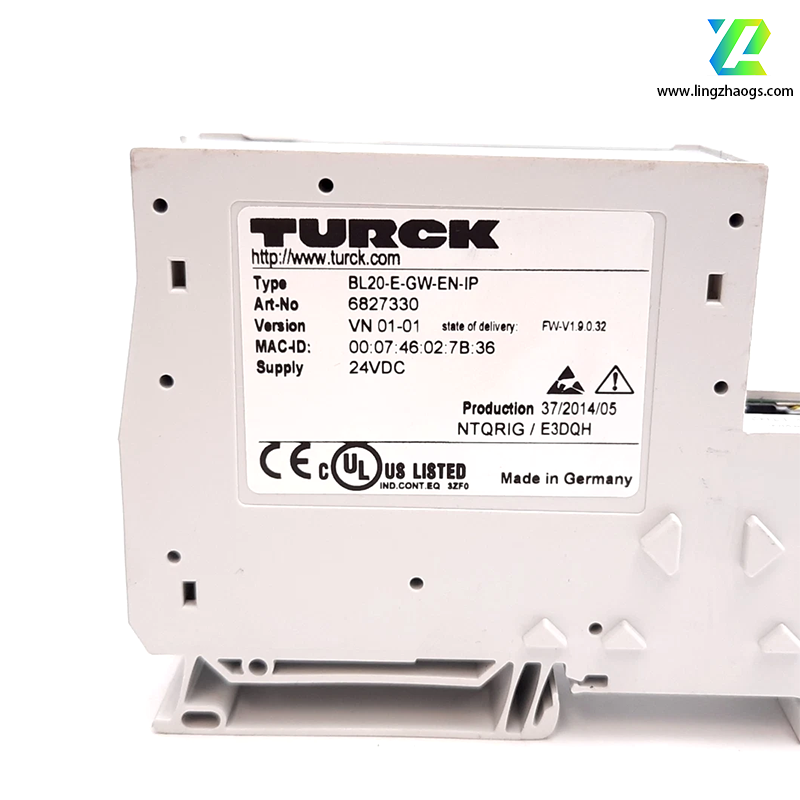
Model: BL20-E-GW-EN-IP
Identification Number: 6827329
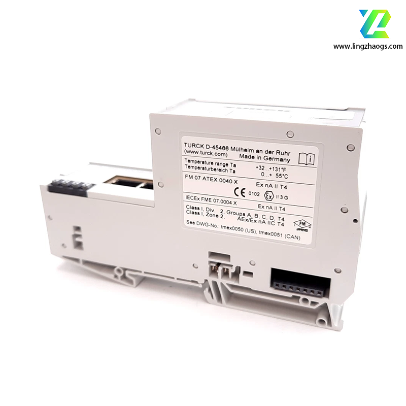
Protection Class: IP20 (suitable for cabinet-mounted installation, protecting against solid objects larger than 12.5mm and preventing accidental finger contact)
2. Appearance and Structure
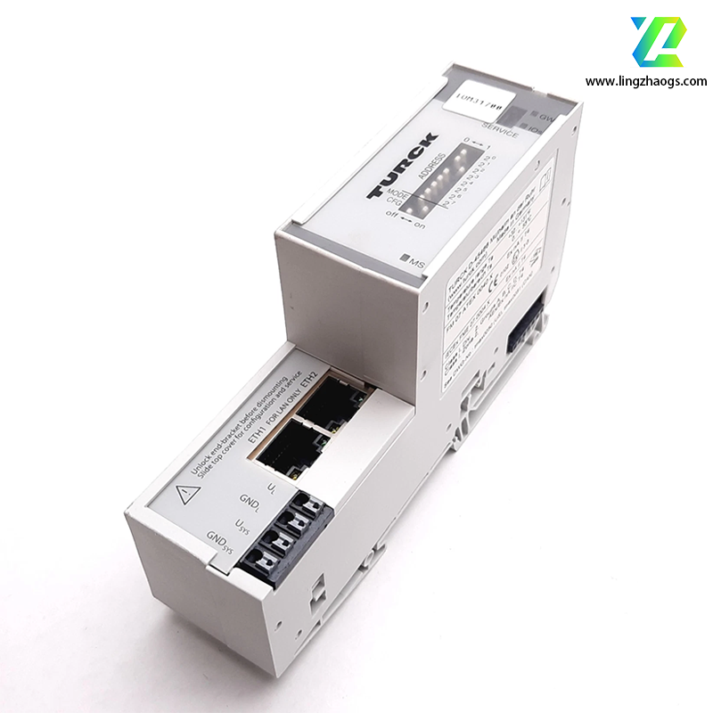
Dimensions: Width of 33.5mm, designed for DIN rail mounting (compatible with standard 35mm DIN rails, enabling space-saving and standardized installation in control cabinets).
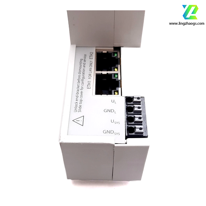
Interfaces:
Equipped with 2 RJ45 ports for fieldbus connection (supporting Ethernet-based communication).
Adopts push-in terminals for power connection (simplifying wiring operations and ensuring reliable contact).
Indicator Lights: Integrates LED indicators for displaying power voltage status, group errors, and bus errors (facilitating real-time visual monitoring of module operation and quick troubleshooting).
3. Functional Features
Multi-Protocol Support: Serves as a multi-protocol gateway between the BL20 system and Ethernet protocols (including Modbus TCP, Ethernet/IP™, and Profinet) — this function is available starting from version VN 03-00.
Profinet supports Fast Startup (FSU) (reducing device startup time for rapid system deployment).
Ethernet/IP™ supports Quick Connect (QC) (accelerating connection establishment between devices).
Integrated Switch: Built-in 10/100 Mbps Ethernet switch (enabling direct cascading of multiple network devices without additional external switches, optimizing network layout).
4. Technical Parameters
Operating Voltage: 24V DC (compatible with standard industrial DC power supplies).
Operating Temperature: 0℃ to +55℃ (adaptable to typical industrial control cabinet environments).
Maximum Connection Capacity: Can connect up to 32 BL20 modules (supporting large-scale I/O expansion to meet complex system configuration needs).
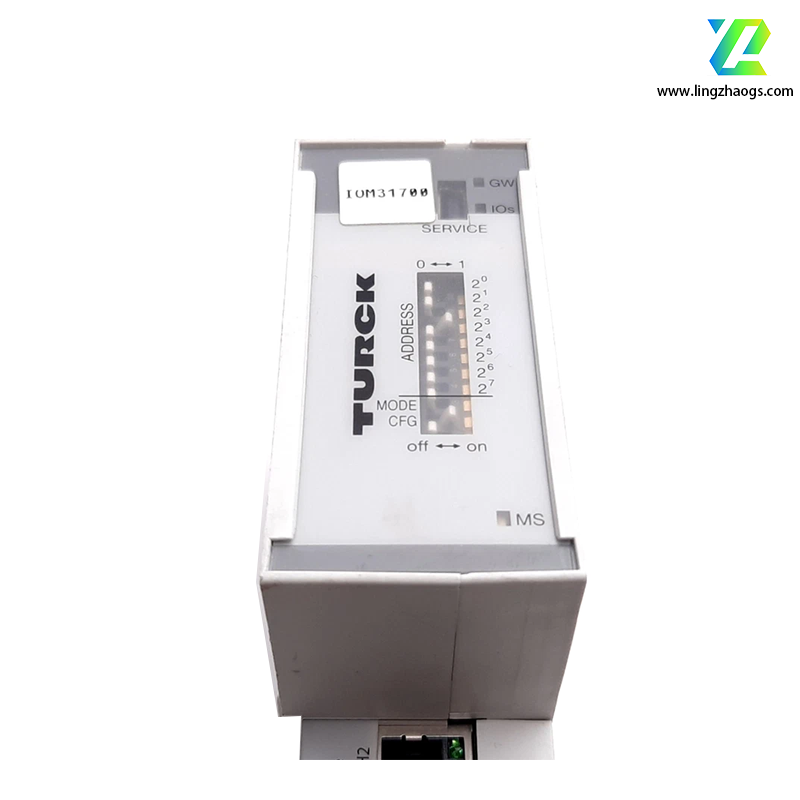
5. Configuration Methods
Web Configuration Interface: Accessible via USB or network connection. Enter the gateway’s IP address in a browser, log in with the default username and password, and configure parameters through the visual interface (user-friendly for centralized and remote settings).
DIP Switch Configuration:
Adjust the CFG DIP switch to the appropriate position to put slave modules into normal working mode.
Set the module’s IP address using the MODE DIP switch and the right-side DIP switch (enabling on-site parameter adjustment without relying on a computer, suitable for scenarios with limited network access).