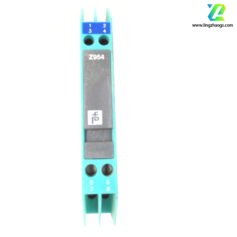
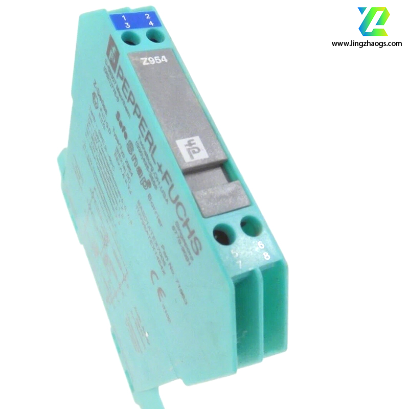
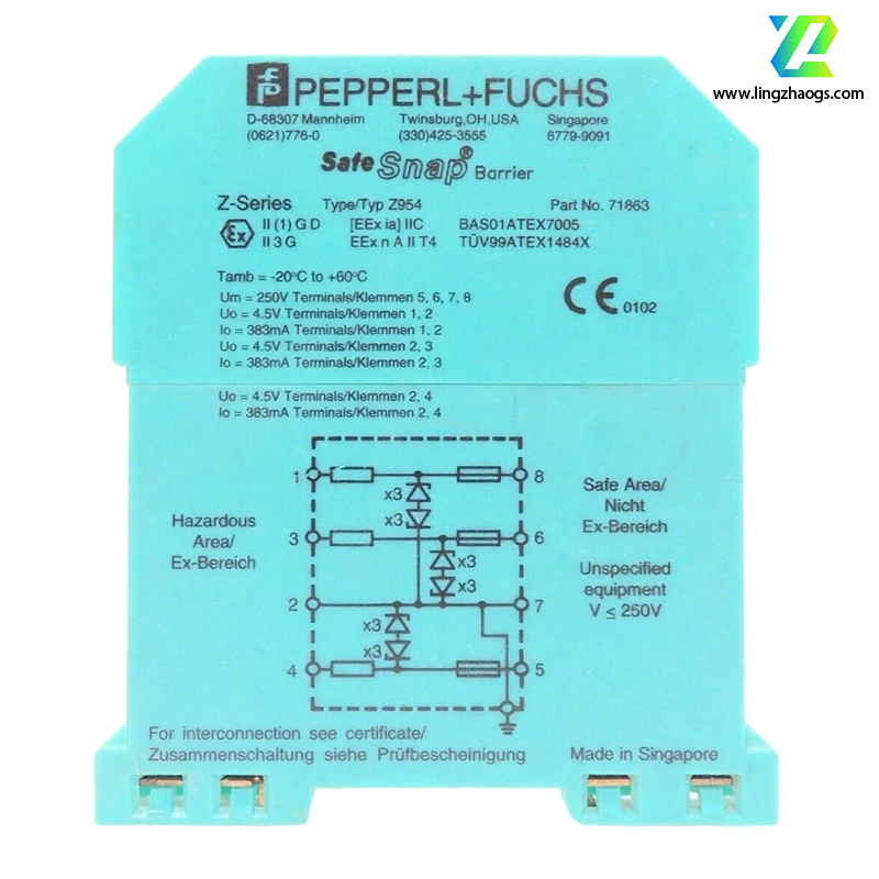
A zener barrier is a device connected between intrinsically safe circuits and non-intrinsically safe circuits. Its core function is to limit the voltage and current supplied to intrinsically safe circuits within a certain safe range. The following takes the Pepperl+Fuchs Z954 as an example for detailed introduction:
Through the combination of zener diodes and current-limiting resistors, it limits the energy in hazardous areas within a safe range, preventing overvoltage or overcurrent from entering the control system. It ensures electrical isolation between hazardous areas and safe areas, complying with the requirements of relevant standards for intrinsically safe equipment. For example, the Z954 limits the short-circuit current to ≤250mA through current-limiting resistors, and at the same time clamps the open-circuit voltage to ≤30V using zener diodes.
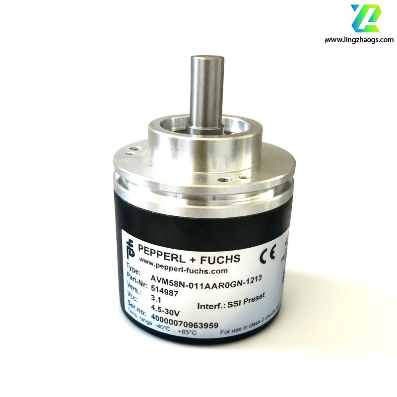
It supports the transmission of low-level mV signals from thermocouples, RTDs (Resistance Temperature Detectors), and bridge circuits, and is compatible with 4-20mA analog or digital inputs, ensuring a signal distortion rate of ≤0.1%. For instance, the zener voltage (V₁₀A) of the Z954 is designed to be 26.5V (for a nominal 24V circuit), which is close to the safe voltage limit of 28V, achieving ideal zener characteristics and reducing the impact of loop leakage current on measurement accuracy.
It adopts a specific circuit structure to effectively suppress common-mode interference, with a Common-Mode Rejection Ratio (CMRR) of ≥120dB (at 1kHz). It has a wide operating temperature range from -20℃ to +60℃, adapting to temperature fluctuations in industrial environments.
When used with thermocouples (e.g., Type K), the Z954 can convert on-site temperature signals into standardized 1-5V or 4-20mA signals and transmit them to the DCS (Distributed Control System). It needs to be paired with a cold-junction compensator (e.g., K-CJC module) to eliminate the impact of ambient temperature changes on measurements.
In chemical reactors, it isolates the mV signals of pressure transmitters, preventing overvoltage caused by lightning strikes or equipment failures from damaging the control system. It supports intelligent transmitters (e.g., HART protocol devices) to ensure the integrity of communication signals.
It serves as a signal isolation device for load cells or strain gauge bridges, enabling high-precision force/displacement measurement. Typical applications include material testing machines or automated production lines.
- DIN Rail Mounting: Supports 35mm standard rails; compact size (approximately 20×119×115mm) and weighs about 150g.
- Terminal Layout: Terminals on the field side and system side are marked with different colors; power terminals support redundant power supply.
- Intrinsically Safe Cable Requirements: Shielded twisted-pair cables must be used, and the distance from non-intrinsically safe cables should be ≥50mm.
- Grounding Requirements: Single-point grounding; grounding resistance ≤1Ω; cross-sectional area of grounding wires ≥2.5mm².
- Parameter Configuration: The signal type (e.g., thermocouple 分度 number) and range can be set through the PW2-ADP1-USB configuration software.
- Troubleshooting: If the LED alarms, check the on-site wiring connections or read the diagnostic code (e.g., 0x8001 indicates an open circuit) using a HART handheld communicator.
For different models of zener barriers, each has a specific meaning. For example, in Z954, "Z" represents a zener barrier, and "954" is the version number or specific configuration code.
Zener barriers must comply with relevant explosion-proof certifications and standards. For example, the Z954 complies with ATEX/IECEx explosion-proof certifications (Ex ia IIC T6) and is suitable for gas explosion-proof Zones 0/1/2 and dust explosion-proof Zones 20/21/22. It also meets the EN 61643-21 surge protection standard.
When matching with PLC/DCS modules, confirm the input impedance matching (e.g., module input impedance ≥10kΩ) to avoid signal attenuation. For intelligent transmitter applications, ensure that the signal bandwidth is within the range supported by the module.
It is recommended to check the grounding resistance and surge counter every 12 months. If the module triggers protection frequently, investigate whether there is a continuous overvoltage source on-site. Meanwhile, clean the optical window (if any) to prevent dust accumulation from affecting signal transmission.
With its high reliability, intrinsically safe explosion-proof characteristics, and flexible signal adaptation capabilities, the Z954 has become the preferred solution for signal isolation in hazardous areas in industrial automation, especially suitable for chemical, power, and pharmaceutical industries with strict requirements for safety and accuracy.