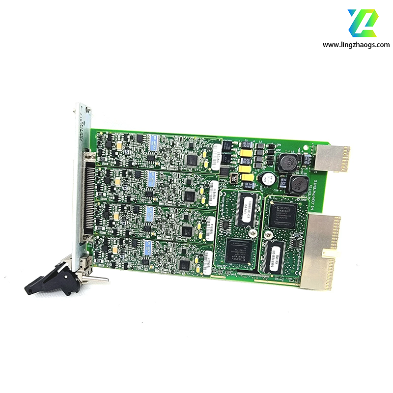
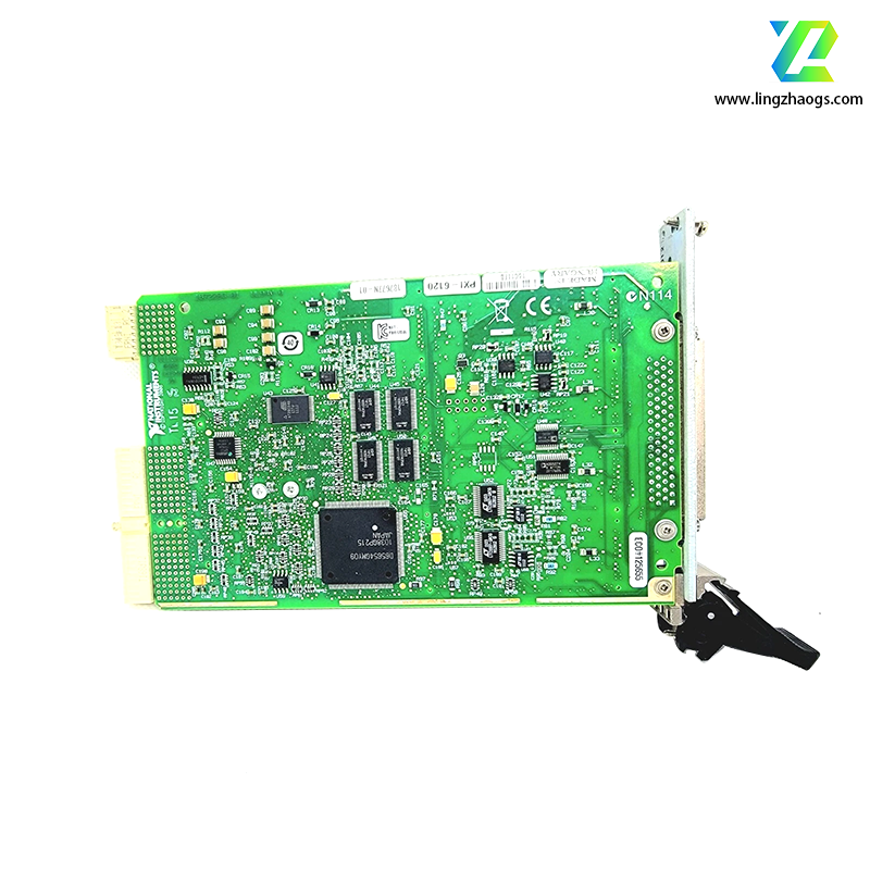
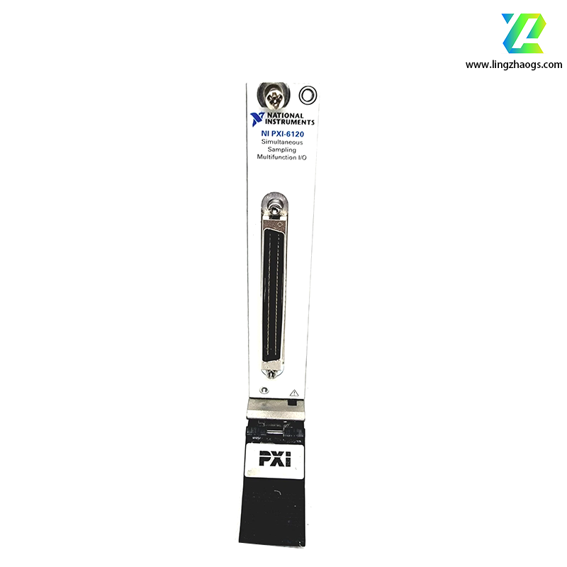
Detailed Specifications of NI PXI-6120 Multifunction DAQ Module
The NI PXI-6120 is a high-performance simultaneous-sampling multifunction data acquisition (DAQ) module belonging to National Instruments (NI)’s S-Series, engineered for hybrid PXI/PXI Express chassis. Its defining features include 4 pseudodifferential analog input channels with dedicated 16-bit ADCs per channel, 800 kS/s per-channel sampling rate (1 MS/s in Warp mode), and 64 MS onboard memory, making it ideal for applications requiring synchronized high-speed signal acquisition—such as automotive 42 V system testing, transient/ballistics measurements, and radar/sonar signal analysis. Integrating analog I/O, digital functions, and precision timing, it delivers reliable performance in dynamic measurement scenarios.
1. Basic Information
- Module Series: S-Series simultaneous-sampling multifunction DAQ module
- Part Numbers: 778396-01 (standard model); 187677C-01, 187677H-01, 187677J-01 (variant models)
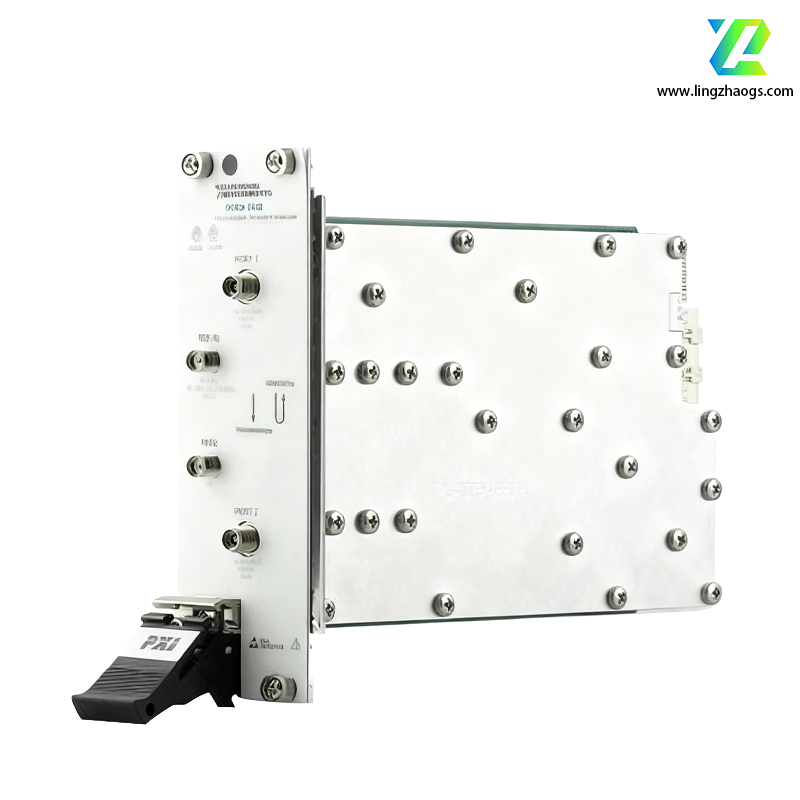
- Physical Dimensions: 1-slot 3U PXI hybrid form factor, compatible with both standard PXI and PXI Express hybrid slots
- Weight: Approximately 6.0 ounces (0.17 kg) (estimated based on S-Series form factor)
- Power Requirements: PXI bus-powered (no external power supply required)
- Interface Type: 68-pin male SCSI-II type connector; PXI hybrid bus interface
- Operating Temperature Range: 0°C ~ 55°C (commercial grade); Storage: -40°C ~ 85°C
- Shock Resistance: 50 g peak (11 ms duration) (consistent with S-Series specifications)
- Vibration Resistance: 2 g RMS (10 Hz ~ 500 Hz) (consistent with S-Series specifications)
- Relative Humidity: 5% ~ 95% (non-condensing)
- Isolation: Non-isolated (signal paths share common ground reference)
- Compliance: Meets FCC Part 15 Class A, CE EN 61326-1, and UL 61010-1 safety & EMC standards
- Warranty & Calibration: 1-year standard warranty; recommended external calibration interval: 2 years
- Note: This module is no longer available from NI; NI recommends the NI PXIe-6124 for new applications
2. Core Technical Specifications
2.1 Analog Input
- 4 pseudodifferential analog input channels (no single-ended mode support)
- Dedicated 16-bit ADC per channel for true simultaneous sampling (no multiplexing)
- Resolution: 16-bit (1 in 65,536), no missing codes
- Standard mode: 800 kS/s per channel (synchronized across all 4 channels)
- Warp mode: Up to 1 MS/s per channel (using external reference clock or onboard counters)
- Input Ranges: 8 software-selectable ranges (200 mV to 42 V) to accommodate diverse signals :
- ±0.2 V, ±0.5 V, ±1 V, ±2 V, ±5 V, ±10 V, ±20 V, ±42 V
- Integral Nonlinearity (INL): ±1 LSB (maximum)
- Absolute Accuracy: 76 mV (typical)
- Noise: As low as 6 µVrms (enabling 90+ dB spurious-free dynamic range)
- ≤±10 V range: 1 MΩ parallel with 100 pF
±10 V range: 10 kΩ parallel with 40 pF
- Common-Mode Rejection Ratio (CMRR): 90 dB (DC ~ 60 Hz)
- Coupling: Software-selectable AC/DC coupling
- Signal Conditioning: Onboard 100 kHz antialiasing filters (software-disablable for transient measurements)
- Buffer Memory: 64 MS onboard memory (32 MS dedicated to analog input, 32 MS to analog output)
2.2 Analog Output
- Channel Count: 2 independent 16-bit analog output channels
- Resolution: 16-bit DAC, integral nonlinearity: ±1 LSB
- Single-channel: Up to 4 MS/s
- Dual-channel (synchronized): 2.5 MS/s per channel
- Output Range: ±10 V (standard), output current: ±5 mA continuous per channel; ±20 mA peak (short-circuit limited)
- Performance: Offset error ±2 mV (typical), gain error ±0.1% of full scale (typical)
2.3 Digital I/O
- Channel Configuration: 8 bidirectional TTL/CMOS-compatible digital I/O lines
- Input: 0 V (low) ~ 5 V (high)
- Output: 0 V (low) ~ 5 V (high), 4 mA source/sink current per line
- Functionality: Hardware-timed digital I/O; supports general-purpose control, status monitoring, and synchronization
2.4 Counter/Timer
- Configuration: 2 independent 24-bit up/down counters
- Timebase: 80 MHz internal clock (stability: ±50 ppm typical)
- Event counting (up to 10 MHz input frequency)
- Frequency/period measurement (resolution: 12.5 ns)
- Pulse width modulation (PWM)
- Pulse generation (custom duty cycle: 0.1% ~ 99.9%)
- External clock sourcing for Warp mode sampling
2.5 Synchronization & Triggering
- Internal: Precision 80 MHz oscillator
- External: 0.1 Hz ~ 10 MHz clock input via front-panel PFI lines
- Phase Locking: Supports PXI chassis phase locking for multi-module synchronization
- Analog Edge Trigger: Rising/falling edge with adjustable threshold (±42 V range)
- Digital Edge Trigger: TTL-compatible edge on digital I/O or PXI trigger lines (0 ~ 7)
- Software Trigger: API-initiated trigger for automated sequences
- Pre/Post Triggering: Configurable trigger position in acquisition buffer (supported via large onboard memory)
- Data Transfer: High-speed DMA (Direct Memory Access) with scatter-gather mode, enabling continuous data streaming
3. Software & Driver Support
- Recommended Drivers: NI-DAQmx (required for full feature access, including Warp mode configuration)
- Programming Compatibility:
- NI Ecosystem: Fully integrated with LabVIEW, LabWindows/CVI, and Measurement Studio; includes LabVIEW examples for Warp mode activation
- Third-Party Languages: Supports Python, ANSI C, C# .NET, and MATLAB (via NI-DAQmx Toolbox)
- Operating Systems: Compatible with Windows (XP/Vista/7/10)
- Configuration Tools: NI Measurement & Automation Explorer (MAX) for channel mapping, filter configuration, and clock routing
- Calibration & Diagnostics:
- Self-calibration support with temperature and timestamp logging
- Onboard temperature monitoring and signal path integrity self-test
- FIFO underflow/overflow detection and error logging
4. Typical Application Scenarios
The NI PXI-6120’s simultaneous sampling and high-speed performance make it ideal for:
- Automotive Testing: 42 V system validation (e.g., battery management, powertrain control) and sensor signal acquisition
- Transient & Ballistics Measurements: Capturing fast-changing signals in explosion testing or projectile dynamics
- Radar/Sonar/Ultrasound: High-bandwidth signal digitization for aerospace and medical imaging systems
- Stimulus-Response Testing: Synchronized analog input, output, and digital I/O for component validation (e.g., amplifier testing)
- High-Energy Physics: Low-noise acquisition of particle detector signals with precise timing
5. Selection & Compatibility Notes
- Ideal Use Cases: Applications requiring 4-channel simultaneous sampling, 800 kS/s+ rates, and large onboard memory; suitable for dynamic signal analysis and transient measurements
- Comparison with S-Series Models:
- vs. NI PXI-6122: PXI-6120 offers 4 channels (vs. 8 channels) but identical sampling rate; choose for lower channel count needs
- vs. NI PXIe-6124 (recommended replacement): PXIe-6124 provides PXI Express bandwidth (vs. PXI) and extended temperature support; ideal for new system designs
- Chassis Compatibility: Works with all NI 3U PXI/PXI Express hybrid chassis (e.g., PXIe-1075) and standard PXI chassis
- Signal Connectivity: Compatible with NI TB-2708 terminal block (SMB connectors for direct analog I/O access)
- Cable Accessories: M-FIT pigtail cables for auxiliary connector access to counters and digital I/O
- Limitations: Non-isolated design (avoid use in high-voltage environments >42 V); no single-ended analog input support; end-of-life status (limited availability)
- Modern Replacement: NI PXIe-6124 (8 channels, 1 MS/s, PXI Express)
- Higher Channel Count: NI PXI-6122 (8 channels, 800 kS/s)
- PCI Form Factor: NI PCI-6120 (identical functionality for desktop test systems)