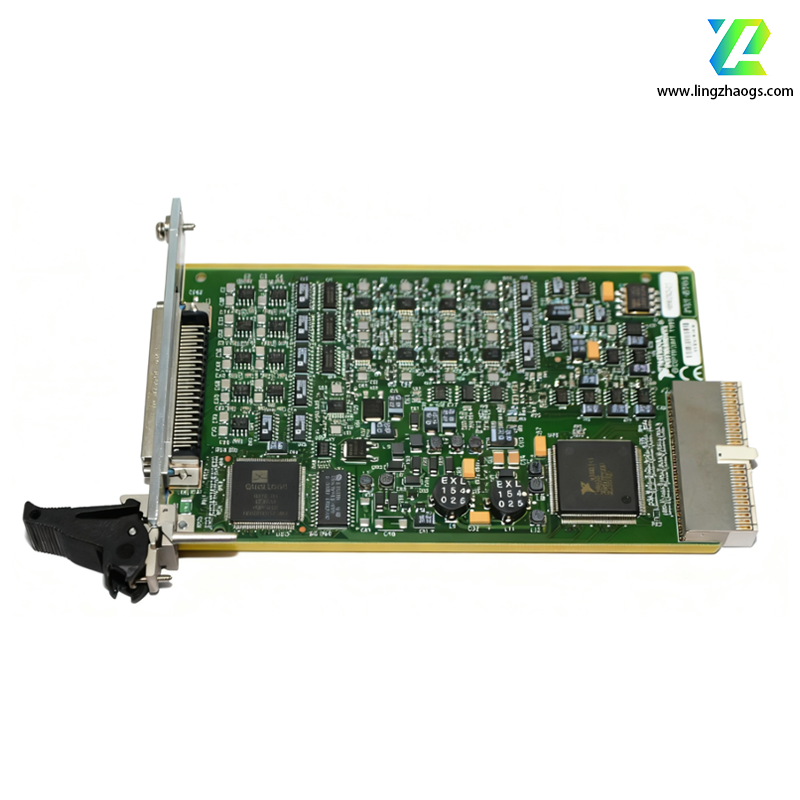
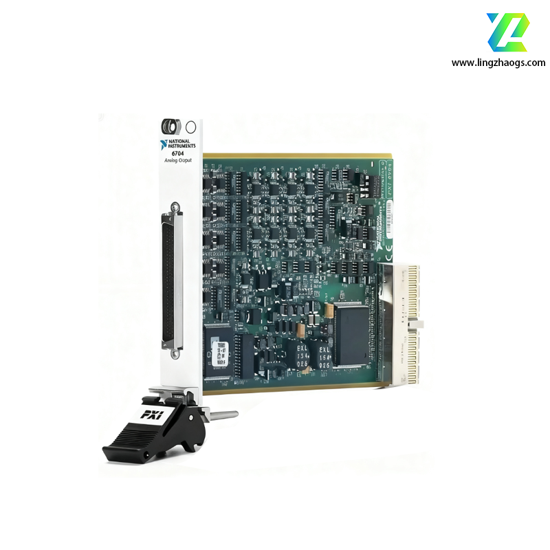
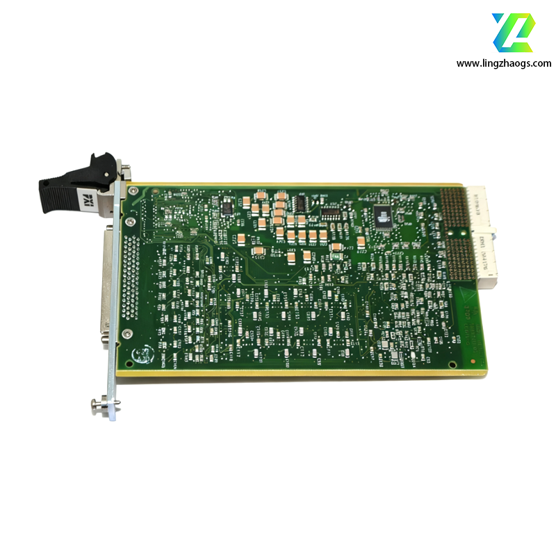
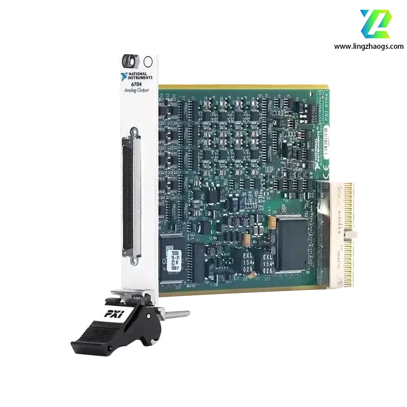
Detailed Specifications of NI PXI-6704 Analog Output Module
The NI PXI-6704 is a high-channel-density analog output module designed for PXI bus architectures, belonging to National Instruments (NI)’s specialized signal generation product line. Its defining feature is 16 independent 16-bit analog output channels with synchronous update capability, making it ideal for applications requiring multi-channel waveform generation, precision voltage control, or coordinated analog stimulus—such as industrial process simulation, automated test equipment (ATE), and aerospace component validation.
1. Basic Information
- Module Series: PXI Analog Output Module, optimized for high-channel-density signal generation
- Part Number: 778065-01 (standard model)
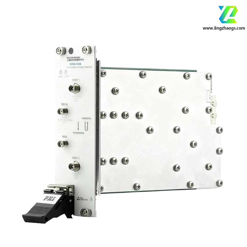
- Physical Dimensions: 1-slot 3U PXI form factor, 10.0 cm × 16.0 cm (width × length)
- Weight: Approximately 5.6 ounces (0.16 kg)
- Interface Type: 68-pin VHDCI (Very High-Density Cable Interconnect) connector, supporting parallel signal routing for 16 analog outputs
- Operating Temperature Range: 0°C ~ 55°C (commercial grade); -40°C ~ 85°C (extended temperature option available)
- Shock Resistance: 50 g peak (11 ms duration)
- Vibration Resistance: 2 g RMS (10 Hz ~ 500 Hz)
- Isolation: Non-isolated (analog outputs share common ground reference)
- Compliance: Meets FCC Part 15 Class A, CE EN 61326-1, UL 61010-1, and IEC 61010-1 safety standards
2. Core Technical Specifications
2.1 Analog Output Subsystem
- Channel Configuration: 16 independent analog output channels, supporting simultaneous synchronous updates
- Resolution: 16-bit DAC (Digital-to-Analog Converter) per channel, with no missing codes (differential nonlinearity: ±0.5 LSB)
- Single-channel: Up to 1 MS/s (mega samples per second)
- Multi-channel (16 channels): 62.5 kS/s per channel (synchronous mode), 1 MS/s per channel (asynchronous mode)
- Output Ranges: 4 software-selectable ranges to match application needs:
- Output Performance Metrics:
- Integral Nonlinearity (INL): ±1 LSB (maximum)
- Offset Error: ±2 mV (typical)
- Gain Error: ±0.1% of full scale (typical)
- Output Impedance: 0.1 Ω (typical), minimizing signal distortion
- Output Current: ±5 mA continuous per channel; ±20 mA peak (short-circuit limited)
- Synchronization: All channels share a common update clock, enabling phase-coherent waveform generation (e.g., multi-phase sine waves for motor control)
- Memory Buffer: 8,192-sample FIFO (First-In-First-Out) per channel, supporting burst-mode waveform generation without CPU intervention
2.2 Digital I/O (Auxiliary)
- Channel Count: 8 auxiliary digital I/O lines (TTL/CMOS-compatible), for status monitoring or trigger control
- Configuration: Software-defined input/output direction per line
- Input: 0 V (low) ~ 5 V (high)
- Output: 0 V (low) ~ 5 V (high), 4 mA source/sink current per line
- Functionality: Supports digital triggering (e.g., initiating analog output updates) and external device status feedback (e.g., verifying actuator position)
2.3 Timing and Triggering
- Internal: 100 MHz precision oscillator (stability: ±50 ppm typical)
- External: 0.1 Hz ~ 1 MHz clock input via front-panel connector
- Digital Edge Trigger: Rising/falling edge on auxiliary digital I/O lines or PXI backplane triggers (PXI_Trig)
- Software Trigger: API-initiated trigger for automated test sequences
- Synchronous Trigger: Coordinates analog output updates with other PXI modules (e.g., DAQ, oscilloscope) via PXI Star Trigger
- Timing Precision: Sub-microsecond channel-to-channel skew (≤100 ns), ensuring synchronized multi-channel output
3. Software and Driver Support
- Recommended Drivers: NI-DAQmx 8.0 and above (required for full feature access); NI-DAQmx Base compatible for cross-platform (Linux, macOS) use
- Programming Compatibility:
- NI Software Ecosystem: Fully integrated with LabVIEW (8.0+), LabWindows/CVI (8.0+), and Measurement Studio (7.1+); includes waveform generation VIs for sine, square, triangle, and arbitrary waveforms
- Third-Party Languages: Supports C/C++, C#, Python (via pyDAQmx bindings), and MATLAB (via NI-DAQmx Toolbox); enables integration with test automation frameworks (e.g., TestStand)
- Configuration Tools: NI Measurement & Automation Explorer (MAX) for graphical channel mapping, range selection, and clock routing
- Diagnostic Features: DAC output verification, FIFO underflow/overflow detection, and digital line status monitoring via driver APIs; supports self-test to validate module functionality
4. Typical Application Scenarios
The NI PXI-6704’s 16-channel design and synchronous output make it ideal for:
- Industrial Process Simulation: Generating multi-channel analog signals to simulate sensor inputs (temperature, pressure, flow) for PLC/DCS testing
- Automated Test Equipment (ATE): Providing analog stimulus for testing multi-channel electronic devices (e.g., data acquisition cards, sensor modules)
- Aerospace and Defense: Simulating avionics sensor signals (e.g., accelerometer, gyroscope outputs) for flight control system validation; generating multi-phase waveforms for radar component testing
- Automotive Electronics: Testing ECU (Electronic Control Unit) inputs (e.g., throttle position, fuel pressure) for engine management systems; simulating battery cell voltages for BMS (Battery Management System) calibration
- Scientific Research: Generating coordinated analog signals for material testing (e.g., stress-strain control via hydraulic actuators); providing precision voltage references for laboratory experiments
5. Selection and Compatibility Notes
- Ideal Use Cases: Applications requiring 8+ analog output channels with synchronous updates, 16-bit resolution, and PXI bus integration; suitable for low-to-medium update rate (≤1 MS/s) scenarios
- Chassis Compatibility: Works with all NI 3U PXI chassis (e.g., PXIe-1075, PXI-1042) and third-party PXI-compliant chassis; no special power or cooling requirements
- Synchronization: Pair with NI PXI-6259 (analog input) for closed-loop control systems (e.g., generating output and measuring response)
- Signal Conditioning: Integrate with NI SCC-68 or SCXI-1125 modules for signal amplification, filtering, or isolation (e.g., extending output range to ±20 V)
- Limitations: Non-isolated design (avoid use in high-voltage environments >10 V); maximum update rate (1 MS/s) lower than specialized waveform generators (e.g., NI PXI-5412)
- Higher Update Rate: NI PXI-6733 (8 channels, 2 MS/s per channel)
- Isolated Outputs: NI PXI-6781 (8 channels, 250 Vrms isolation)
- More Channels: NI PXI-6708 (32 channels, 16-bit, 100 kS/s per channel)
- PCI Form Factor: NI PCI-6704 (identical functionality for desktop test systems)