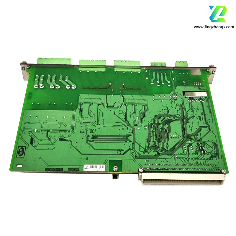
Here’s a detailed overview of DEIF SCM4.1 (DEIF A/S part number) based on industrial power system references, third-party distributor data, and DEIF’s core focus on genset synchronization and power management. As an advanced synchronization module, this part aligns with DEIF’s offerings for precise grid-genset and genset-genset coordination in marine, industrial, and power generation applications. For official specifications, consult DEIF A/S directly.
- Brand: DEIF A/S (a global provider of power control, monitoring, and automation solutions)
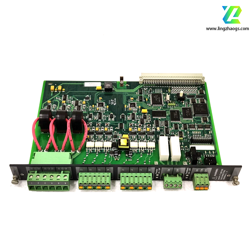
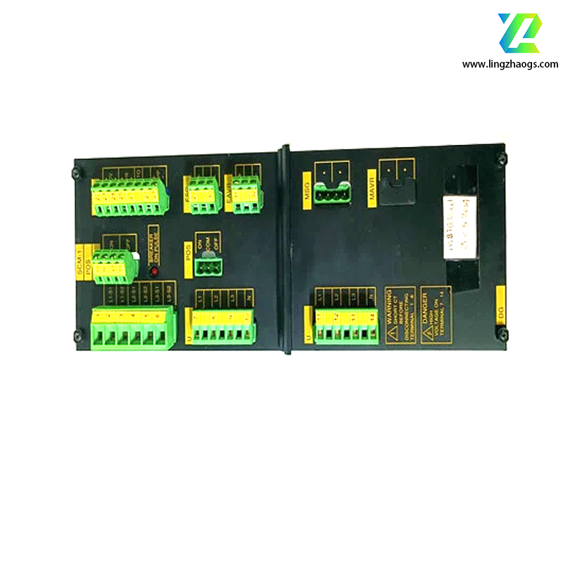
- Model: SCM4.1
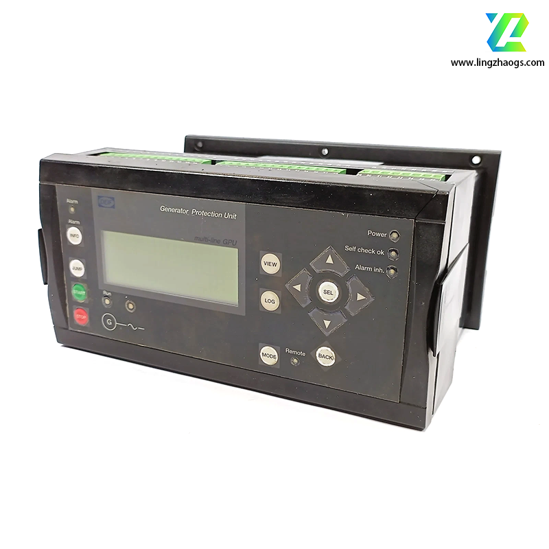
- Type: Advanced Synchronization Control Module
- Industry: Marine (merchant ships, offshore vessels), power generation (diesel/gas gensets, microgrids), industrial backup power (data centers, factories), and utility-scale power distribution.
- Function: Enables high-precision synchronization of generators (gensets) with an existing power grid or parallel-operating gensets. It monitors key electrical parameters (voltage, frequency, phase angle, and phase sequence) of the incoming generator and the target grid, automatically adjusts the generator’s speed (via governor control) and voltage (via exciter control) to match grid conditions, and issues a “close breaker” command only when all synchronization criteria are met. This ensures shock-free parallel operation, preventing equipment damage (e.g., alternator winding damage) and grid instability (e.g., voltage/frequency fluctuations).
Enhanced Synchronization Precision & Control
- Monitors four critical synchronization parameters with configurable, tight tolerance thresholds (adjustable via DEIF PC-Tool software):
- Voltage Matching: Aligns genset output voltage with the grid (tolerance range: ±0.5–5% of rated voltage, suitable for sensitive industrial loads).
- Frequency Matching: Regulates genset speed to match grid frequency (tolerance: ±0.01–0.2 Hz for 50/60 Hz grids) via proportional-integral (PI) control signals to the governor.
- Phase Angle Alignment: Ensures genset voltage waveform is in phase with the grid (tolerance: ±1–3 degrees), minimizing inrush current during breaker closing.
- Phase Sequence Verification: Built-in phase sequence detection to prevent catastrophic damage from reverse-phase synchronization (a critical safety feature missing in basic modules).
- Supports “slip frequency control” to manage the rate of phase angle convergence, ensuring smooth synchronization even with large initial parameter deviations.
Dual-Channel & Multi-Mode Operation
- Dual-Channel Capability: Can independently synchronize two separate gensets or a single genset with two alternative grids (e.g., main grid and emergency grid in marine systems), reducing the need for multiple modules.
- Flexible Control Modes:
- Automatic Mode: Fully autonomous synchronization (initiates parameter adjustment and breaker closing) for unmanned systems or remote operation.
- Semi-Automatic Mode: Operators approve breaker closing via HMI/SCADA after the module confirms synchronization readiness.
- Manual Mode: Operators manually adjust genset speed/voltage with real-time parameter feedback (e.g., phase difference LED indicators) for hands-on control.
- Synchronization Check Relay (SCR) Function: Failsafe to block breaker closing if parameters fall out of tolerance, even if a manual command is issued.
Seamless System Integration & Monitoring
- Communicates with DEIF genset controllers (e.g., DGC-2020, DGC-300), power management systems (PMS 400/600), and HMs via standard industrial protocols:
- Modbus RTU/TCP: For data exchange with SCADA systems or third-party PLCs.
- DEIF Proprietary Protocol: Optimized for low-latency communication with DEIF’s PMS and controllers.
- Real-time data logging (stores up to 1,000 synchronization events with timestamps) for post-incident analysis and compliance reporting (critical for marine and industrial safety audits).
Marine-Grade Reliability
- Built to withstand harsh marine and industrial environments:
- Compliant with IEC 60945 (marine electronics) and certified by DNV GL, ABS, Lloyd’s Register (LR), and Bureau Veritas (BV) for shipboard use.
- Resistant to vibration (IEC 60068-2-6), shock (IEC 60068-2-27), salt spray (IEC 60068-2-52), and electromagnetic interference (EMC compliance with IEC 61000-6-2/4).
Electrical Parameters
- Power Supply: 24V DC (nominal, standard for DEIF modules), with a wide tolerance range of 18–32V DC to accommodate voltage fluctuations in genset power systems.
- Power Consumption: ≤12W under full load (varies with active channels and communication activity).
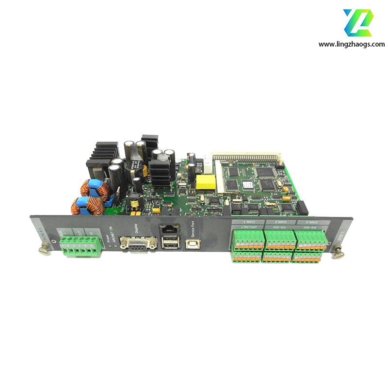
- Input Signals:
- Voltage Inputs: 2 independent 3-phase channels (100V/230V/400V AC) for grid and genset voltage measurement; compatible with voltage transformers (VTs) for medium-voltage (MV) grids.
- Control Inputs: 6 digital inputs (24V DC) for mode selection (auto/manual), synchronization start/stop, and external interlocks.
- Output Signals:
- Analog Outputs: 4 x 4–20 mA signals (2 per channel) for governor (speed control) and exciter (voltage control) actuation.
- Relay Outputs: 8 configurable relays (2A @ 250V AC / 30V DC) for breaker closing, synchronization ready, fault alarms, and interlock signals.
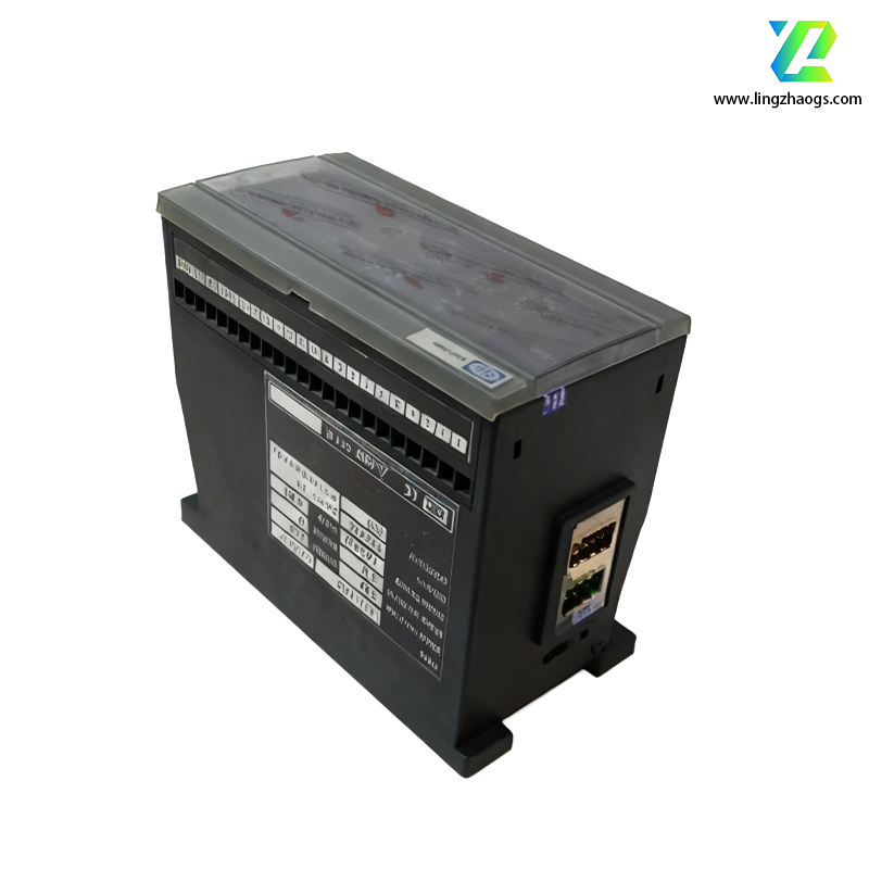
Physical & Environmental Attributes
- Form Factor: Rack-mount design (19-inch, 1U high), compatible with DEIF’s standard control cabinets and marine switchboards.
- Dimensions: Approximately 483 mm (width) × 44 mm (height) × 200 mm (depth) (1U form factor).
- Environmental Ratings:
- Operating Temperature: -25°C to +70°C (suits extreme climates, from arctic offshore platforms to tropical engine rooms).
- Humidity: 5–95% (non-condensing), resistant to moisture in marine/industrial settings.
- Ingress Protection (IP): IP20 (when mounted in a control cabinet) — protected against dust and accidental contact.
Performance Metrics
- Synchronization Time: Typically <5 seconds (from start command to breaker closing) for small parameter deviations; <15 seconds for large deviations (e.g., 1 Hz frequency difference).
- Measurement Accuracy:
- Voltage: ±0.2% of full scale.
- Frequency: ±0.005 Hz.
- Phase Angle: ±0.5 degrees.
- Response Time: <100 ms for parameter measurement and control signal output (critical for fast-changing grid conditions).
- Condition: Available as new OEM (through DEIF A/S or authorized distributors) or genuine refurbished (via specialized suppliers like Marine Controls, Power Systems International).
- Warranty: 24-month warranty for new units (standard for DEIF products); refurbished units typically include a 12-month warranty.
- Documentation:
- Technical datasheets, wiring diagrams, and configuration guides are accessible to DEIF customers via DEIF’s customer portal.
- DEIF provides training and software tools (e.g., DEIF PC-Tool) for module setup, calibration, and troubleshooting.
- Compatible Systems:
- DEIF Genset Controllers: DGC-2020, DGC-300, DGC-600.
- DEIF Power Management Systems: PMS 400, PMS 600.
- Third-party gensets (Caterpillar, Cummins, MTU) and circuit breakers (ABB, Siemens) via standard analog/digital signals or Modbus.
- Similar DEIF Models:
- DEIF SCM-1: Basic single-channel synchronization module (no phase sequence verification, for small-scale applications).
- DEIF SCM4.2: Advanced variant of the SCM4 series with additional communication ports (e.g., Ethernet/IP) and enhanced data logging.
Setup Requirements:
- Mount in a 19-inch rack with 1U clearance; ensure minimum 50 mm ventilation space above/below to prevent overheating. For marine applications, install in a weatherproof control cabinet compliant with IEC 60092.
- Configure via DEIF PC-Tool to set synchronization thresholds, map input/output signals, and enable dual-channel operation (if required). Calibrate voltage inputs with VTs to match the grid’s rated voltage.
Wiring Guidelines:
- Use shielded, twisted-pair cables for voltage inputs and control signals to minimize EMI interference from genset alternators or shipboard electrical systems.
- For governor/exciter control outputs (4–20 mA), use twisted-pair cables and keep wiring lengths <100 meters to avoid signal degradation. Ground shields at the module end only to prevent ground loops.
Safety & Troubleshooting:
- Follow lockout-tagout (LOTO) procedures when wiring or servicing the SCM4.1—incorrect synchronization can cause phase opposition, leading to catastrophic generator or breaker failure.
- Use front-panel LED indicators and HMI data to diagnose issues:
- Flashing Blue: Synchronization in progress (channel 1).
- Solid Green: Synchronization ready (breaker closing approved).
- Red: Fault (e.g., phase sequence mismatch, voltage out of range).
- For synchronization failures, verify VT connections, check governor/exciter responsiveness, and confirm threshold settings in DEIF PC-Tool. Phase sequence errors require correcting wiring at the voltage inputs.
- Dual-Channel Limitation: The SCM4.1’s dual channels are independent but share a single power supply and communication interface. A module-wide fault (e.g., power loss) will affect both channels—use redundant modules for mission-critical applications (e.g., nuclear power plant auxiliaries).
- VT Compatibility: Ensure voltage transformers (VTs) are sized to match the module’s input range (100V/230V/400V AC). Undersized/overized VTs will cause inaccurate voltage measurements and synchronization failures.
- Genuine Parts Only: Use genuine DEIF SCM4.1 modules for safety-critical applications. Aftermarket alternatives may not meet marine certifications (e.g., DNV GL) or precision standards, risking unsafe parallel operation.
For further technical assistance, contact DEIF A/S’s global support team or your local authorized service provider. Always validate specifications against your generator’s rated parameters and grid synchronization requirements before installation.